49 Warehouse Sectional Doors: Track and Clearance Planning
A 49-door warehouse package required different track arrangements around beams, cable trays and fire-service pipework. SEPPES coordinated six opening groups, selected-location opening limits and control-box positions before manufacture and equipment dispatch.
- Door package
- 49 sectional doors
- Opening groups
- 6 configurations
- Panel thickness
- 40 mm
- Factory dispatch
- November 2026
The track path had to be coordinated for each opening group.
The supply model was equipment manufacture with remote technical support. The project contractor organised site installation, so clear opening identification and coordinated drawings were central to the package.
The Site Challenge
A multi-level warehouse project in China had large loading and access openings with different overhead conditions. Beams, cable trays and fire-service pipes occupied parts of the door travel envelope.
- 49 doors distributed across six dimensional and clearance groups.
- Nominal opening heights of 4,500 mm.
- Restricted rear space and service conflicts at selected locations.
The SEPPES Response
SEPPES coordinated high-lift track arrangements with the project teams and manufactured the door package around the agreed opening schedule.
- Site dimensions reviewed with the contractor and factory detail team.
- Selected openings planned around a 4,200 mm opening limit.
- Relocated control boxes and extension cabling where required.
Six groups kept different site conditions visible in one package.
The groups shared a 4,500 mm nominal height, but their widths and service conflicts differed. Grouping the openings helped prevent one track arrangement from being assumed suitable for every location.
| Opening group | Quantity and nominal opening | Main coordination condition |
|---|---|---|
| Group 1 | 4 doors · 3,600 W × 4,500 H mm. | Beam underside at 5,500 mm; higher pipework also included in the section review. |
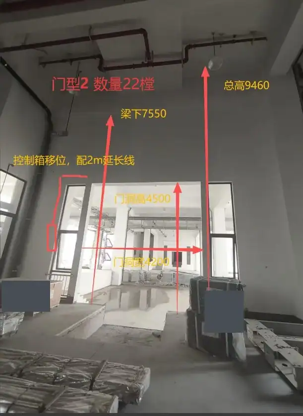
| Group 2 | 22 doors · 4,200 W × 4,500 H mm. | Beam underside at 7,550 mm; control-box relocation with a 2 m extension cable. |
| Group 3 | 2 doors · 3,600 W × 4,500 H mm. | Fire-service pipe height at 6,690 mm. |
| Group 4 | 2 doors · 6,400 W × 4,500 H mm. | A pipe conflict at 4,100 mm rear depth; 4,200 mm opening-limit arrangement. |
| Group 5 | 6 doors · 3,600 W × 4,500 H mm. | Cable tray at 4,900 mm and beam underside at 5,500 mm. |
| Group 6 | 13 doors · 4,200 W × 4,500 H mm. | A pipe conflict at 4,100 mm rear depth; 4,200 mm opening-limit arrangement. |
The selected survey photograph shows the Group 2 condition: a 4,200 mm-wide by 4,500 mm-high opening, a beam at 7,550 mm and a control-box relocation note. The schedule totals 49 doors.
A 4,500 mm opening does not automatically provide 4,500 mm operating clearance.
In this project, selected openings were coordinated around an opening limit of 4,200 mm while their nominal height remained 4,500 mm. Keeping those values separate makes the practical access requirement easier to assess.
| Dimension or requirement | What it describes | How to use it in a project brief |
|---|---|---|
| Nominal opening height | The scheduled building-opening dimension. | Record it separately from the required usable clearance and the final door-open position. |
| Usable opening clearance | The space available below the door in its approved open position. | Check it against the actual loaded vehicle or equipment envelope and the facility’s required clearance. |
| Track and panel travel envelope | The space the moving door, curves and horizontal tracks require. | Show beams and services in a section drawing, including their distance behind the opening. |
| Selected-location opening limit | A 4,200 mm opening-limit arrangement at Groups 4 and 6. | Treat this as a location-specific design decision. It is not a general setting for the other openings. |
If a vehicle requires more usable height than the coordinated layout can provide, return to the building and door design review. Changing an operating limit is not a substitute for checking the required access envelope.
Prepare the elevation and section information using the industrial door installation and clearance checklist.
The complete moving system needs space, not only the door panel.
The design coordination involved the door panels, tracks, drive and controls as one installation envelope. A width-and-height schedule alone could not describe those interfaces.
Track Routing and Mounting
The package used tailored high-lift track arrangements around the surveyed beam and service positions. The review included the lift section, track curve, rear travel space and support locations.
For another warehouse, request the proposed track and mounting arrangement against the actual building section. Include the space needed to install, inspect and maintain the complete system.
Panels, Controls and Access
The selected door panels were 40 mm polyurethane-filled insulated steel panels. Control boxes were repositioned at the relevant openings, with extension cabling supplied for the Group 2 arrangement.
Confirm accessible control positions, cable routes, electrical supply and the final door-open position before equipment manufacture.
Drawing agreement came before the factory package was released.
The case focuses on survey, drawing coordination and factory supply. For a contractor-installed package, the installation team needs the same labelled opening information used during manufacture.
Survey and Identify Each Opening
The team reviewed beam, tray and pipe dimensions with the contractor and grouped the 49 openings by their relevant conditions.
Coordinate the Nonstandard Layouts
The contractor and factory detail team reviewed track routing, selected opening limits and control-box relocation requirements.
Manufacture and Check the Equipment
The agreed schedule was used to prepare the door package and factory checks, with the associated delivery and equipment information.
Dispatch and Support Site Installation
The equipment package was dispatched in November 2026. SEPPES provided remote technical support while the project contractor organised installation.
Choose the routing around the building section and operating requirement.
These are review directions for a new project, rather than interchangeable configurations. Ask the supplier to confirm the offered arrangement at each identified opening.
| Site condition | Design direction to review | Important input |
|---|---|---|
| Usable headroom above the opening | A high-lift arrangement coordinated with the available structure. | Headroom, beam underside, track support and the full door travel envelope. |
| Clear vertical space along the wall | Whether a vertical-lift arrangement suits the opening. | Complete wall height, service positions and maintenance access. |
| Limited headroom or rear space | A suitable alternative track arrangement or door structure. | A measured section showing both overhead and rear obstructions. |
| Pipes or trays within the proposed travel path | A coordinated track layout and building-services review. | The obstacle’s height, depth, width and position relative to the finished floor and opening. |
Measure the section as well as the front elevation.
This checklist is for planning another warehouse package. A section sketch with a labelled obstacle is usually more useful than a photograph containing only the door-opening dimensions.
Opening and Obstacle Information
- Labelled clear widths and heights, with the finished floor used as a consistent reference.
- Beam undersides, tray edges and pipe routes with heights and distances behind the opening.
- Side-room, fixing faces, track-support positions and nearby equipment.
- Photographs from the front, side and the intended rear travel area.
Access and Installation Information
- Largest loaded vehicle or equipment and the usable clearance the facility requires.
- Who supplies structural supports, power, access equipment and site labour.
- Control-box position, cable route and any relocation requirement.
- Survey approval, drawing revision, site-ready date and installation sequence.
Make the approved arrangement traceable to the installed opening.
For another contractor-installed project, agree these responsibilities before shipment so the site team does not need to reconstruct the design decisions from equipment labels.
Before Installation
Match the delivered equipment and approved drawing to the labelled opening. Confirm that the surveyed services and floor conditions have not changed and that the responsible teams have agreed the supports and access needed.
At Commissioning
Have qualified installers verify the travel, limits, controls and protective devices against the approved arrangement. Confirm and document the actual usable opening, operating instructions and route for technical support.
Clarify the operating clearance before the track layout is approved.
Is the nominal door height the same as the usable opening?
Not necessarily. Confirm the actual approved door-open position and the resulting clear space. This project used a 4,200 mm opening-limit arrangement at selected 4,500 mm-high openings.
Can the same track drawing be used across a large door package?
Only after the relevant conditions have been checked. This project used six groups because width, beams, trays, pipework and rear-space conditions differed.
Can an installer simply adjust the limit to avoid a pipe?
The complete arrangement needs approval first. A limit change must remain consistent with door travel, the required usable clearance and the agreed installation design. It is not a replacement for coordinated drawings.
Did SEPPES perform all on-site installation in this project?
The package was supplied with remote technical support; the project contractor organised site installation. Confirm the supply, installation and commissioning responsibilities for your own order.
What is the most useful drawing for a clearance review?
Provide a labelled elevation and section showing the finished floor, opening, beam, tray and pipe positions, rear depth and required vehicle envelope. Include clear site photographs and the current building-services revision.
Coordinating sectional doors around beams and building services?
Send a labelled opening schedule, dimensioned section views and photographs of beams, trays and pipes. Include the vehicle clearance you need and the agreed installation responsibilities for a track-layout review.