Custom Industrial Door Installation & Retrofit Planning
An opening width and height do not describe the space a door needs to travel, mount and be serviced. Use cross-project examples to prepare a site survey, coordinate obstructions and define the installation responsibilities before manufacture.
- Measure
- The opening & section
- Confirm
- Usable clearance
- Coordinate
- Structure & services
- Agree
- Installation & handover
Measure what the door needs around the opening.
A useful survey connects the access requirement to the complete moving and mounting envelope. This is the starting point for either a new building or a retrofit.
Start with the Required Passage
Record the clear width and height and explain what must pass through the opening. Include the largest loaded vehicle, trolley or equipment and the route used to approach it.
Keep the facility’s required usable clearance separate from a nominal building or door dimension. The approved open position is part of the access review.
Map the Installation Space
Show the fixing surfaces, headroom, side space and rear depth. Add the location of beams, trays, pipes, equipment and areas needed for service access.
A dimensioned section makes overhead and rear-space conflicts easier to discuss than a front photograph alone. Use the same labelled reference for the survey and the supplier drawing.
Give each measurement a clear reference and purpose.
Use these as survey categories for a new project. The supplier and responsible building teams should agree which details and tolerances are needed for the selected equipment.
| Survey item | Useful detail | Why it changes the review |
|---|---|---|
| Clear opening | Width, height and finished-floor reference for each labelled location. | Defines the passage to be reviewed and avoids confusing similar-looking openings. |
| Headroom and side space | Beam underside, wall edges and the available drive and guide area. | Influences the complete installation envelope and motor arrangement. |
| Rear travel space | Depth behind the opening and obstacles within the proposed travel zone. | Helps assess sectional-door track routing and access around the equipment. |
| Fixing structure | Wall or panel construction, steelwork and proposed mounting faces. | Identifies which supports and fixing details need confirmation with the responsible building team. |
| Building services | Heights and positions of pipes, trays, lights and other obstructions. | Allows the door layout and services to be coordinated on the same section. |
| Controls and site access | Control-box location, cable route and access for installation and maintenance. | Clarifies electrical work, relocation needs and the space that must remain available. |
Confirm the access envelope in the approved open position.
A dimensional schedule is necessary, but it does not replace the review of how the door will actually sit and move at the opening.
The warehouse case used 4,500 mm nominal opening heights, while selected locations were coordinated around a 4,200 mm opening-limit arrangement. Those values describe different things: the scheduled opening and the planned door-open position.
For another site, compare the usable opening with the actual loaded vehicle or equipment envelope and the facility’s required clearance. If that requirement cannot be met, return to the door and building layout review before approving manufacture.
| Question | What to check | Useful drawing or confirmation |
|---|---|---|
| Will the required load pass? | The complete loaded envelope and the usable passage. | A layout and approved open-position dimension. |
| Will the door travel clear of services? | The moving panels or curtain, track curves, drive and supports. | A section showing the travel envelope and surveyed obstructions. |
| Can the installation be serviced? | Cover removal, control access and nearby equipment. | The installation envelope with agreed access space. |
Different openings create different coordination tasks.
These cases cover track and service conflicts, a compact drive layout, a corridor redesign and loading-area civil works. Open the case that matches the constraint at your site.
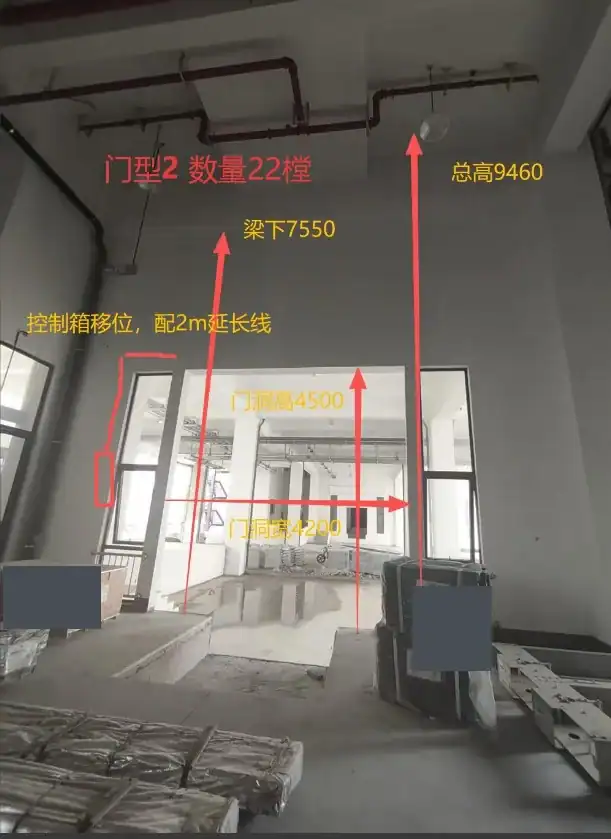
49-Door Warehouse Clearance Plan
Six opening groups were coordinated around beams and services. Selected 4,500 mm-high openings used a 4,200 mm opening-limit arrangement.
Confirm usable clearance separately from nominal opening height.
Read the Warehouse Clearance Project →
Three-Door Cleanroom Interlocking
Three 2,000 × 2,000 mm doors combined a compact internal-motor layout with door-to-door interlocking and status indication.
Review the door relationship and installation envelope together.
Read the Cleanroom Interlock Project →
Textile Corridor Opening Review
A 12-door package adopted 5,500 × 4,000 mm openings after reviewing the initial width proposal. Control terminals were reserved for later AGV connections.
Separate today’s door package from future integration work.
Read the Textile Corridor Project →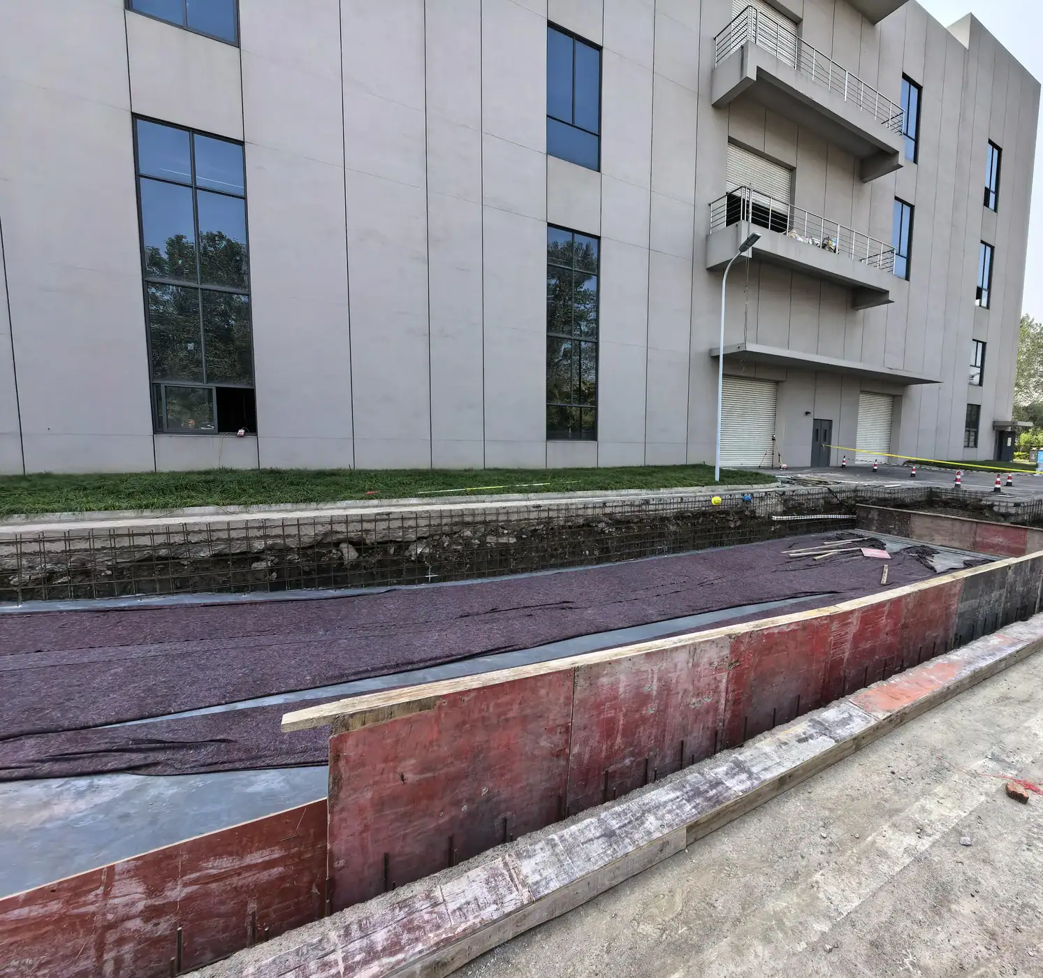
Leveler and Shelter Package
Two hydraulic levelers and two mechanical dock shelters were coordinated with pit works and installation at a finished-goods warehouse.
Connect equipment selection with vehicle data and civil-work interfaces.
Read the Dock Equipment Project →Review an alternative when the site condition changes.
These are review directions, not a list of interchangeable solutions. The selected configuration needs to be coordinated with the actual site and operating requirement.
| Site condition | Configuration direction to discuss | What to confirm before selection |
|---|---|---|
| Limited side space | Whether an internal-motor layout suits the required door package. | Complete head and side dimensions, mounting and service access. |
| Beams or services above a sectional-door opening | A coordinated lift and track arrangement. | Available height, rear depth, supports and usable opening clearance. |
| A large or exposed corridor opening | Opening requirements and a suitable door construction. | Required traffic space, temporary and final exposure, structure and declared performance for the offered size. |
| An existing partition or processing passage | The door-to-wall junction and material configuration. | Fixing faces, finishing responsibilities, cleaning exposure and control positions. |
| A loading position requiring a pit | The selected leveler and its approved civil-work interface. | Construction drawing, tolerances, embedded details and readiness approval. |
Where a door connects to other equipment, also review the automation and interlocking interface guide.
Plan around the condition that will exist at installation.
The drawing is only useful if it reflects the relevant site stage. Make the survey date, drawing revision and final-measurement decision traceable.
For a New Building
Identify which concrete, steelwork, floor finishes, cladding and service routes are complete when the survey is taken. Agree when final measurements are approved and which team reports later changes.
Include temporary exposure if doors may be used before the enclosure is finished. The textile corridor follow-up shows why that condition belongs in the operating review.
For an Existing Facility
Describe the current opening, surrounding equipment and restrictions on access or working periods. Identify what needs to be removed, retained or coordinated, with responsibility assigned to the relevant contractor.
Plan the work sequence and operating arrangements with the facility team. Do not assume the building condition in an old drawing still matches the site.
Use the same opening labels throughout the project.
This is a planning sequence for a new project. It is intended to organise the decisions and responsibilities, rather than replace the equipment’s installation instructions.
Capture the Site Brief
Combine the opening schedule, measured sections, photographs and the required access envelope.
Resolve the Interfaces
Review the door layout against structure, services, control positions and maintenance access with the responsible teams.
Approve the Configuration
Agree the final dimensions, drawing revision, installation scope and site-readiness conditions before manufacture.
Check the Site and Hand Over
Confirm that the site still matches the approved arrangement, then complete the agreed installation, operating checks and documentation.
Send enough information to review the complete opening.
Use this checklist to prepare a new enquiry. Where multiple openings differ, keep the conditions separate instead of copying one set of measurements across the package.
Measurements and Site Context
- Labelled opening schedule with width, height and quantity.
- Section sketches showing headroom, rear depth and service positions.
- Photographs of the front, sides, fixing faces and travel area.
- Vehicle or load envelope and the usable clearance required by the facility.
Programme and Responsibility
- Site stage, relevant drawing revision and when final measurements can be approved.
- Who supplies structure, civil works, electrical work and access equipment.
- Who installs and commissions the door package.
- Required handover information and the route for technical support.
For loading bays, combine the site survey with the door and dock systems planning checklist.
Verify the installation against the agreed arrangement.
A useful handover leaves the operator with the information needed to use and support the installed arrangement. The project’s installation and supply model should be clear before work starts.
At Installation and Commissioning
Have qualified installers check the equipment and its travel against the approved drawing and the selected configuration. Confirm the usable open position, controls, protective devices and access to service points.
Keep the results and final settings with the labelled opening schedule.
For the Facility Team
Request operating instructions, equipment identification, approved drawings, relevant cleaning guidance and the service contact. Agree inspection and maintenance arrangements using the manufacturer’s guidance and the site duty.
Review later changes to services, equipment routes or the building enclosure before they affect the installation.
Resolve the installation assumptions before ordering.
Is a width-and-height measurement enough?
It is a starting point. The review also needs the mounting structure, headroom, side space, travel depth, services and the required usable passage. A labelled section and photographs make those conditions easier to coordinate.
Can a high-lift layout avoid every pipe conflict?
No layout should be assumed suitable without review. The pipe position, track travel, supports, usable clearance and service access must be coordinated for the actual opening.
Can the operating limit simply be changed to create clearance?
A limit setting belongs within the approved installation arrangement. It needs to remain consistent with the equipment’s travel and the facility’s required usable passage. Return to the design review where those requirements conflict.
Can building services be moved instead?
Ask the responsible building and services teams to review that option. Changes to structural or fire-service elements require their own approval and should not be treated as a door-installer decision.
When should final measurements be approved?
Agree the relevant site-readiness stage with the supplier and contractors. Record which floor, structure and services are complete and how changes after approval will be reported.
What if the order is equipment supply with remote support?
Confirm the local installer, commissioning responsibility, drawing package and technical-support route before shipment. The warehouse case shows this supply model rather than SEPPES carrying out all site installation.
Review the installation conditions before finalising the door.
Send a labelled opening schedule, section sketches and clear site photographs. Include the required usable passage, nearby services and installation responsibilities so SEPPES can review the relevant layout and equipment options.