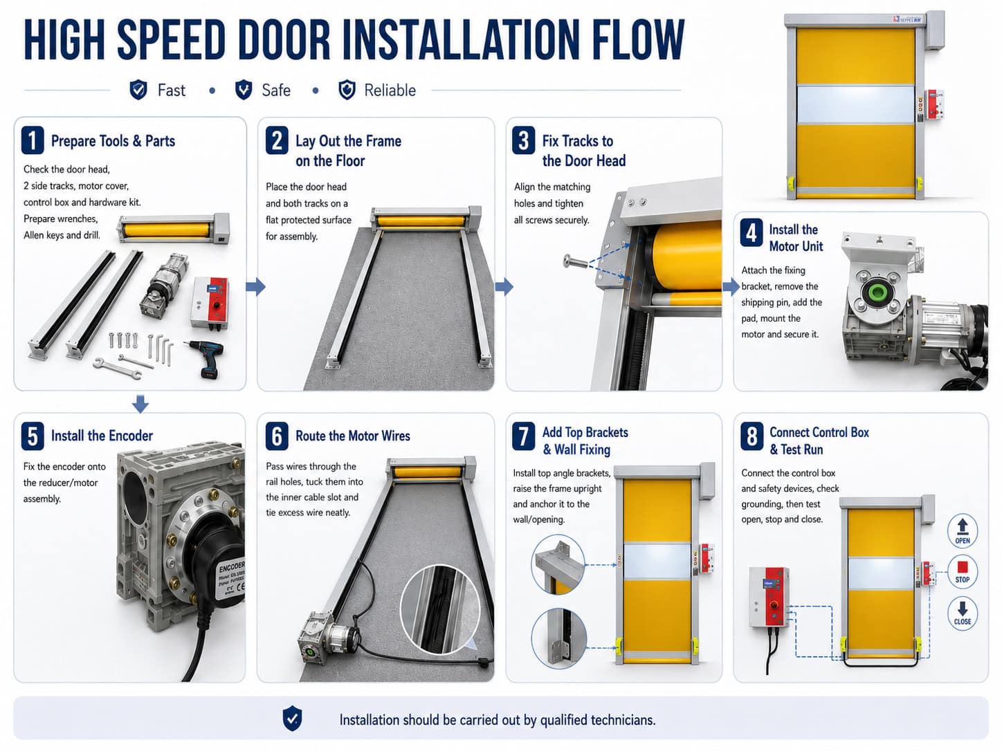
Installer correctement une porte rapide à enroulement ne consiste pas seulement à fixer un cadre à une ouverture. L'installateur doit vérifier les composants livrés, assembler et ancrer la porte d'équerre, installer correctement l'entraînement et l'encodeur, protéger et mettre à la terre le système électrique, aligner les dispositifs de sécurité, régler les fins de course et tester chaque mode de fonctionnement avant la mise en service.
Ce document manuel d'installation de porte à grande vitesse explique le processus complet pour la configuration de la porte rapide à enroulement en PVC/toile SEPPES présentée dans notre manuel d'utilisation des portes industrielles. Il est destiné à servir de référence pratique pour les installateurs formés, les ingénieurs de projet, les entrepreneurs et les équipes de maintenance des installations.
Avis de sécurité important : Les portes rapides sont des équipements industriels motorisés. L'installation, les travaux électriques, la mise en service, la maintenance et les réparations doivent être effectués par un personnel qualifié et formé. Un électricien qualifié doit réaliser les travaux électriques conformément au schéma de câblage fourni et aux réglementations locales applicables. Le plan de projet approuvé et le manuel spécifique au modèle fourni avec la porte prévalent toujours sur ce guide général.
Installation de la porte rapide en un coup d'œil
Utilisez ce guide manuel d'installation de porte à grande vitesse dans l'ordre suivant :
- Isolez la zone de travail et confirmez le plan d'installation approuvé.
- Inspectez l'expédition et identifiez chaque composant.
- Vérifiez l'ouverture, la structure de support, les dégagements, le côté moteur et l'alimentation électrique.
- Assemblez le caisson supérieur et les guides latéraux sur une surface plane et protégée.
- Installez le moteur, le raccordement du réducteur et l'encodeur absolu.
- Acheminez et fixez les câbles du moteur et de l'encodeur.
- Levez, alignez et ancrez l'ensemble de la porte à la structure de support.
- Installez le coffret de commande, la mise à la terre, les capteurs de sécurité et les dispositifs d'activation.
- Confirmez le sens de fonctionnement et réglez les fins de course d'ouverture et de fermeture.
- Testez l'arrêt d'urgence, les dispositifs de sécurité, les commandes d'activation et les cycles répétés.
- Installez tous les capots, documentez les réglages et formez l'opérateur.
Ne mettez pas la porte sous tension simplement parce que l'assemblage mécanique semble complet. La porte n'est prête à être utilisée qu'après avoir testé les dispositifs de sécurité et les fins de course, et après que l'installation a réussi une inspection de mise en service documentée.
1. Vérifier que ce manuel correspond à votre porte
Ce guide couvre l'installation générale d'une porte rapide à enroulement à rideau souple SEPPES avec :
- Un caisson supérieur ou coffre de porte contenant le rideau et l'enrouleur
- Deux rails de guidage latéraux avec balais d'étanchéité
- Un moteur et un réducteur montés latéralement
- Un encodeur absolu
- Un coffret de commande électrique
- Capteurs de sécurité photovoltaïques
- Des dispositifs d'activation spécifiques au projet, tels que boutons-poussoirs, radar, détecteur à boucle, cordon de tirage ou télécommande
La position du moteur peut être à gauche ou à droite lorsqu'on regarde depuis le côté d'installation. Confirmez le côté moteur commandé avant l'assemblage. Une porte rapide spirale, une porte de congélateur isolée, une porte à empilement, une porte à fermeture éclair ou toute autre configuration spéciale peut utiliser une structure et une procédure d'installation différentes. Demandez le plan spécifique au modèle correct si les composants fournis ne correspondent pas à la disposition décrite ici.
2. Exigences de sécurité avant l'installation
Mettez en place une zone d'exclusion autour de la porte avant de déballer ou d'assembler la porte. Tenez les travailleurs, les véhicules, les enfants, les animaux et les équipements non liés à l'écart de la zone d'installation.
Respectez ces exigences tout au long des travaux :
- Seul un personnel qualifié peut installer, mettre en service, entretenir ou réparer la porte.
- Coupez et isolez l'alimentation électrique principale avant tout travail mécanique ou électrique.
- Avant le câblage, maintenez l'alimentation coupée pendant plus de 10 minutes et attendez que le voyant de la carte de commande se soit éteint.
- Ne travaillez jamais avec les mains mouillées. Utilisez un équipement de protection individuelle isolant approprié pour les travaux électriques.
- Ne vous tenez pas, ne marchez pas et ne placez pas d'outils sous le rideau ou l'ensemble de la porte pendant l'installation, les tests, l'ouverture ou la fermeture.
- Ne laissez personne traverser l'ouverture pendant que le rideau est en mouvement.
- Gardez le sol et toute la zone de déplacement du rideau dégagés.
- Ne modifiez pas le programme du contrôleur, le circuit de sécurité, la configuration de la porte ou les composants fournis sans autorisation.
- Ne démontez pas le contrôleur et ne remplacez pas de pièces sans l'approbation de SEPPES ou d'un prestataire de services agréé.
L'équipe d'installation doit également respecter l'évaluation des risques du site, le plan de levage, la procédure de consignation/déconsignation et les exigences locales applicables en matière d'électricité et de construction.
Pour les projets aux États-Unis, les installateurs et les employeurs doivent également consulter les exigences officielles de l'OSHA concernant le Contrôle de l'énergie dangereuse (consignation/déconsignation) D'autres pays et régions peuvent imposer des règles différentes ou supplémentaires.
3. Inspection de livraison et liste des pièces
Chaque porte industrielle est inspectée avant expédition, mais les dommages de transport ou les colis manquants doivent être identifiés avant le début de l'installation. Comparez la livraison avec la liste de colisage et la commande approuvée.
L'expédition standard décrite dans le manuel SEPPES comprend :

| Composant | Ce qu'il faut inspecter |
|---|---|
| Caisson supérieur/coffre de porte avec rideau | Bosses, rayures, dommages au rideau, dommages à l'enrouleur ou à l'arbre |
| Rails de guidage gauche et droit | Rectitude, balais d'étanchéité, trous de fixation, rainures de passage des câbles |
| Moteur et capot moteur | Vérifier le côté moteur, l'état du connecteur et du câble, ainsi que tout dommage visible |
| Système de commande électrique | Spécification d'alimentation correcte, boîtier et boutons non endommagés |
| Boîte de matériel/accessoires | Vis de fixation, support de fixation du moteur, patin en caoutchouc, goupille d'arbre, équerres et autres éléments de fixation fournis |
| Ensemble capteur de sécurité photovoltaïque | Émetteur, récepteur/réflecteur, câbles, supports et fixations |
| Commandes en option | Radar, détecteur de boucle, cordon de traction, télécommande, airbag/bord de sécurité, interverrouillage ou autres accessoires commandés |
Ne pas jeter la goupille d'arbre moteur ou les petits patins comme matériau d'emballage. Séparer et étiqueter le matériel avant l'assemblage. Si la commande est incomplète, si le côté moteur est incorrect ou si une pièce critique est endommagée, arrêter et contacter le fournisseur avant de percer ou d'alimenter la porte.
4. Vérifications du site et de l'ouverture
Le plan approuvé doit définir la dimension de l'ouverture, la hauteur libre, l'espace latéral, la position du moteur, la position du boîtier de commande, les points de fixation et l'alimentation électrique requise. Revérifier ces conditions sur site, car une porte précise ne peut pas compenser une ouverture inadaptée ou hors d'équerre.
Avant l'assemblage, confirmer :
- La largeur et la hauteur de passage libre correspondent au plan approuvé.
- Le mur porteur ou la structure en acier est adapté aux ancrages spécifiés et aux charges de fonctionnement.
- Le linteau, le sol et les surfaces de fixation sont complets et exempts de matériaux détachés.
- Il y a suffisamment de hauteur libre pour le caisson supérieur, le moteur, les capots et l'accès de maintenance.
- Il y a suffisamment d'espace latéral du côté moteur sélectionné.
- Le sol et le mur environnant sont suffisamment de niveau et d'aplomb pour l'alignement.
- Les tuyaux, chemins de câbles, éclairages, sprinklers, convoyeurs et autres équipements n'entrent pas en conflit avec la porte.
- L'emplacement du contrôleur est visible, accessible et protégé du trafic et de l'eau.
- L'alimentation électrique réelle correspond à la plaque signalétique de la porte et au plan électrique du projet.
- La ligne des capteurs de sécurité est dégagée et les dispositifs d'activation sont adaptés au parcours de circulation.
Ne pas choisir les ancrages uniquement par habitude. Le type, la taille, la quantité et la profondeur d'ancrage dépendent du matériau de support et de la conception approuvée du projet.
5. Outils et équipements
Le manuel d'utilisation SEPPES répertorie des clés de 12, 13, 14 et 17 mm, un jeu de clés Allen et un jeu de forets pour l'assemblage de base. L'installateur aura normalement également besoin d'équipements de mesure et d'accès adaptés au site.
Préparer :
- Clés ou douilles de 12, 13, 14 et 17 mm
- Jeu de clés Allen
- Perceuse électrique et forets adaptés au matériau de support
- Mètre ruban, équerre, niveau à bulle ou laser, et outils de vérification d'aplomb
- Ancrages approuvés et outils de fixation spécifiés pour le projet
- Équipements de levage et d'accès adaptés
- Équipements de gestion des câbles et de test électrique
- Dispositifs de consignation/déconsignation et équipements de protection individuelle requis
Utiliser uniquement des équipements non endommagés et correctement calibrés. Protéger le cadre peint et le tablier du sol, des arêtes vives, des copeaux de perçage et des débris de soudure.
PVC High Speed Door Installation Video Guide
Watch this practical PVC high speed door installation demonstration to understand the general assembly process, including frame positioning, guide rail installation, motor assembly, and system setup. Follow the step-by-step instructions below for more detailed installation guidance.
Video Disclaimer: This third-party video is provided for general installation reference only. Installation procedures may vary by manufacturer and door model. For SEPPES products, please follow the official installation instructions and technical drawings provided with your order.
6. Manuel d'installation de la porte rapide, étape par étape
Étape 1 : Préparer une zone d'assemblage plane
Trouver une zone propre et plane suffisamment grande pour le cadre complet de la porte. Poser du carton, un film protecteur ou une autre couche non abrasive sur le sol pour éviter les rayures.
Placer le caisson supérieur et les rails de guidage dans l'orientation indiquée sur le plan fourni. Le manuel SEPPES recommande de poser le caisson et les rails face vers le bas/inversés sur le sol pour faciliter la connexion initiale. Confirmer le côté moteur avant de fixer quoi que ce soit.

Étape 2 : Connecter les guides latéraux au caisson supérieur
Aligner les trous de fixation correspondants des rails de guidage gauche et droit avec les trous du caisson supérieur. Insérer les vis fournies, engager d'abord toutes les fixations, puis les serrer uniformément avec la clé appropriée.
Vérifier que :
- Les guides gauche et droit sont du bon côté.
- Les entrées des guides sont alignées avec le chemin du tablier.
- Les rails de guidage ne sont pas torsadés.
- Les joints caisson-guides sont complètement en place.
- Toutes les vis de connexion sont serrées et aucun câble n'est coincé.
À ce stade, les trois parties principales doivent former un ensemble rigide en forme de U.
Étape 3 : Assembler le support de fixation du moteur
Localiser le support/la base de fixation du moteur dans la boîte d'accessoires. Le fixer au moteur avec les quatre vis fournies comme indiqué dans le manuel spécifique au modèle.
Ne pas soulever ou porter le moteur par ses câbles. Maintenir le connecteur du moteur, le câble de frein, le câble de l'encodeur et l'interface d'arbre propres et protégés.
Étape 4 : Connecter le moteur à l'arbre de la porte
Le manuel SEPPES montre une goupille de retenue fixée par ruban adhésif sur l'arbre du moteur pour le transport. Retirer le ruban adhésif, conserver la goupille pour l'installation et positionner le patin en caoutchouc fourni sous l'ensemble moteur.
Aligner le réducteur avec l'arbre de la porte et le faire glisser en position sans marteler ni forcer les pièces. L'arbre de la porte doit pénétrer à plus de la moitié de la profondeur de la connexion du réducteur. Installer la quincaillerie de retenue et serrer les vis de fixation inférieures.
Avant de continuer, confirmer que :
- Le moteur est soutenu par le support et le patin corrects.
- Le moteur et l'arbre de la porte sont alignés.
- L'engagement de l'arbre est supérieur à la moitié de la profondeur du réducteur.
- La goupille de retenue et les vis de fixation sont installées.
- Aucun câble n'est étiré, pincé ou acheminé à travers une pièce mobile.
Étape 5 : Installer l'encodeur absolu
Le système de contrôle de course utilise un encodeur absolu externe. Insérer la base du capteur magnétique de l'encodeur dans le réducteur et s'assurer qu'elle est proche de la face d'extrémité du réducteur. Fixer solidement l'encodeur au réducteur à l'aide des vis fournies, puis insérer et serrer la prise aviation.
Une position incorrecte de l'aimant, une prise desserrée, un câblage endommagé ou un encodeur endommagé peuvent provoquer un défaut d'encodeur ou empêcher un réglage précis des limites de course. Ne pas frapper l'encodeur ni tirer sur le câble pendant l'installation.
Étape 6 : Acheminer les câbles du moteur et de l'encodeur
Faire passer les fils du moteur à travers le premier trou rond du rail de guidage, les acheminer à l'intérieur du rail et les faire ressortir par le deuxième trou rond, en suivant la disposition indiquée dans le manuel fourni.
Placer les fils complètement à l'intérieur de la goulotte interne de routage des câbles. Fixer tout câble excédentaire afin qu'il ne puisse pas toucher le tablier, le rouleau, l'arbre, le chemin de guidage ou les points de fixation. Protéger le câble à chaque ouverture métallique et maintenir la séparation requise entre le câblage de puissance et le câblage de signal.
Étape 7 : Installer les équerres de fixation de la traverse supérieure
Installez les équerres de fixation fournies en haut de la traverse supérieure. Le manuel SEPPES montre des équerres aux deux extrémités et, lorsqu'elles sont prévues, au milieu de la traverse.
Engagez les fixations, vérifiez l'orientation des équerres et serrez-les solidement. Ces équerres font partie de la liaison entre la traverse et la structure porteuse ; ne les omettez pas et ne les remplacez pas par du matériel non approuvé.
Étape 8 : Lever, positionner et ancrer la porte
Levez la porte assemblée selon la méthode approuvée sur site et avec un équipement adapté. Suivez le plan de levage du projet et maintenez toute personne hors des zones de chute et de mouvement.
Positionnez la porte autour de l'ouverture structurelle. Vérifiez le niveau de la traverse supérieure, l'aplomb des deux guides latéraux, la régularité de l'écartement des guides et l'équerrage du cadre complet. Les supports temporaires doivent maintenir l'ensemble en toute sécurité pendant la pose des ancrages permanents.
Fixez les équerres supérieures et les guides latéraux au mur porteur ou au cadre en acier approuvé, puis complétez les points de fixation inférieurs/au sol requis. Serrez les ancrages selon une séquence contrôlée et revérifiez l'alignement après serrage.
La porte installée doit être stable, de niveau et solidement reliée au mur ou au cadre d'installation. Un cadre déformé peut créer des frottements, un déplacement irrégulier du rideau, une mauvaise étanchéité, une usure prématurée et un désalignement peu fiable des cellules de sécurité.
Étape 9 : Installer le boîtier de commande et réaliser les raccordements électriques
Montez le boîtier de commande à l'emplacement approuvé, où l'opérateur peut utiliser l'arrêt d'urgence en toute sécurité et observer la porte sans se tenir dans sa trajectoire.
Les travaux électriques doivent être réalisés par un électricien qualifié à l'aide du schéma de câblage spécifique au modèle. Le manuel exige que le moteur et le contrôleur soient correctement mis à la terre. Il spécifie un conducteur de terre en cuivre d'au moins 3,5 mm² et une résistance de mise à la terre inférieure à 10 ohms. Il exige également un dispositif de protection contre les fuites avec un courant de déclenchement de 0,03 A, ou un système d'alimentation protégé équivalent.
Respectez les précautions suivantes concernant le contrôleur :
- Vérifiez que l'alimentation correspond à la plaque signalétique et au plan du projet.
- Isolez l'alimentation pendant plus de 10 minutes avant le câblage et attendez que le voyant de la carte s'éteigne.
- Mettez à la terre le moteur et le contrôleur.
- N'installez pas de contacteur électromagnétique, de condensateur d'absorption ou tout autre dispositif d'absorption résistance-capacité entre le contrôleur et le moteur.
- N'effectuez pas un autre test de tenue en tension sur le contrôleur.
- Protégez, identifiez et éloignez les câbles des pièces mobiles.
- Ne mettez pas le système sous tension avec les capots ouverts, sauf si la procédure de mise en service autorisée l'exige spécifiquement.
Le schéma de câblage fourni et le code local applicable prévalent s'ils diffèrent des valeurs générales ci-dessus.
Étape 10 : Installer les dispositifs de sécurité et d'activation
Installez l'émetteur et le récepteur/réflecteur de sécurité photovoltaïque sur les côtés opposés de l'ouverture. Alignez-les précisément, serrez leurs supports, protégez leurs câbles et assurez-vous que le faisceau n'est pas obstrué par le cadre, l'état du sol, les matériaux stockés ou les équipements de circulation normaux.
Connectez les dispositifs d'activation commandés aux bornes définies dans le schéma du contrôleur fourni. Selon le projet, ceux-ci peuvent inclure :
- Poste à boutons-poussoirs
- Radar ou détecteur de mouvement
- Détecteur géomagnétique/à boucle inductive pour véhicules
- Interrupteur à cordon tiré
- Appuyer sur la télécommande pour ouvrir la porte.
- Interrupteur cyclique à clé unique
- Bandeau de sécurité inférieur ou coussin de sécurité
- Interverrouillage ou signal de gestion technique du bâtiment/automatisation
Ne pontez pas, ne contournez pas et ne désactivez pas une entrée de sécurité pour faire fonctionner la porte.
Étape 11 : Confirmer le sens de déplacement et régler les fins de course
Dégagez la baie et maintenez tout le personnel hors de la zone de mouvement. Utilisez le mode jog autorisé du contrôleur pour confirmer que la commande d'ouverture déplace le rideau vers le haut et que la commande de fermeture le déplace vers le bas.
Réglez les positions d'origine, d'ouverture totale et de fermeture totale conformément à la version du contrôleur fournie avec la porte. Évitez de régler la fin de course basse de manière trop agressive, ce qui pourrait comprimer, plier ou enfoncer la barre inférieure dans le sol. Évitez de régler la fin de course haute trop haut, ce qui pourrait placer le rideau, la barre inférieure ou les barres anti-vent dans une position dangereuse dans la traverse supérieure.
Si la porte se déplace dans la mauvaise direction, ne trouve pas sa position d'encodeur ou signale un défaut de fin de course/d'encodeur, arrêtez la mise en service et vérifiez le câblage approuvé et la procédure du contrôleur. Ne faites pas fonctionner le moteur de manière répétée contre une fin de course incorrecte.
Étape 12 : Mettre en service et tester la porte
La mise en service doit prouver que le système complet fonctionne en toute sécurité, et pas seulement que le moteur tourne. Testez au minimum les éléments suivants :
- Boutons d'ouverture, de fermeture, d'arrêt et d'arrêt d'urgence.
- Sens d'ouverture et de fermeture corrects.
- Fins de course d'ouverture totale et de fermeture totale.
- Réponse de la sécurité photovoltaïque pendant un cycle de fermeture.
- Réponse du bandeau de sécurité/coussin de sécurité, s'il est installé.
- Radar, détecteur à boucle, cordon tiré, télécommande, interverrouillage ou autre dispositif d'activation commandé.
- Guidage du rideau dans les deux guides.
- Position et étanchéité de la barre inférieure.
- Fonctionnement du moteur, du réducteur et de l'encodeur sans bruit anormal, vibration ou surchauffe.
- Plusieurs cycles répétés avec la baie dégagée.
Le manuel précise qu'un dispositif photovoltaïque mal aligné peut empêcher la porte de se fermer, car le système de commande interprète l'absence de faisceau comme une condition dangereuse. Corrigez l'alignement ; ne contournez jamais le capteur.
Étape 13 : Poser les capots et finaliser la remise
Après la réussite de tous les tests, isolez l'alimentation comme requis, posez les capots du moteur et de la traverse supérieure, retirez les outils et les débris de perçage, et remettez en état la zone de travail.
Consignez :
- Modèle de porte et numéro de série
- Tension d'alimentation et version du contrôleur
- Côté moteur
- Réglages finaux des fins de course
- Résultats des tests des dispositifs de sécurité
- Dispositifs d'activation installés
- Date d'installation et de mise en service
- Coordonnées de l'installateur et de l'électricien
- Toute dérogation approuvée par rapport au plan
Remettez au propriétaire le manuel spécifique au modèle, le schéma de câblage, les instructions de maintenance et le contact de service. Formez les opérateurs autorisés aux commandes normales, à l'arrêt d'urgence, aux vérifications visuelles quotidiennes, à l'utilisation en toute sécurité et au signalement des défauts. Conservez le manuel près de la porte et facilement accessible.
7. Liste de contrôle d'inspection de l'installation de la porte rapide
Utilisez ce guide manuel d'installation de porte à grande vitesse Liste de contrôle avant la signature de la remise :
| Point d'inspection | Critères de réussite |
|---|---|
| Expédition | Les composants correspondent à la commande ; aucun dommage non résolu ni pièce de sécurité manquante |
| Châssis | Niveau de la tête ; guides d'aplomb, d'équerre, parallèles et sans torsion |
| Fixations | Tête, guides, connexions murales/châssis et points de mise à la terre sécurisés |
| Moteur | Bon côté, support et patin installés, engagement de l'arbre correct, fixations serrées |
| Codeur | Aimant correctement positionné, codeur sécurisé, connecteur aviation serré |
| Câbles | Protégés, fixés dans les chemins de câbles, étiquetés et dégagés des pièces mobiles |
| Électricité | Alimentation correcte, isolation, mise à la terre, protection et armoires fermées |
| Trajet du rideau | Le rideau se déplace en douceur, sans frottement, accrochage ni obstruction |
| Fin de course | Positions pleinement ouvert et pleinement fermé réglées correctement |
| Dispositifs de sécurité | Arrêt d'urgence, cellules photovoltaïques et bord/airbag optionnel testés |
| Activation | Tous les boutons-poussoirs, capteurs, télécommandes ou interverrouillages commandés fonctionnent correctement |
| Capots et zone | Capots installés ; ouverture propre ; étiquettes d'avertissement visibles |
| Remise en service | Manuel fourni, essais consignés et opérateurs formés |
Si un élément est non conforme, maintenir la porte hors service jusqu'à ce qu'un technicien qualifié corrige et re-teste l'élément.
8. Erreurs d'installation courantes à éviter
Assemblage du mauvais côté du moteur
Les dispositions moteur à gauche et à droite ne sont pas interchangeables à la dernière minute. Confirmer le plan approuvé avant de raccorder les guides et la tête.
Mise au rebut de la goupille d'arbre ou du patin en caoutchouc
Les petites pièces de montage du moteur peuvent être collées ou emballées séparément. Les identifier lors de l'inspection de livraison et les installer conformément au manuel fourni.
Engagement insuffisant de l'arbre
Le manuel exige que l'arbre de la porte pénètre sur plus de la moitié de la profondeur du réducteur. Un engagement insuffisant peut provoquer un mauvais alignement ou des dommages à la transmission.
Ancrage d'un châssis hors d'équerre
Serrer les ancrages avant de vérifier le niveau, l'aplomb et l'équerrage peut tordre les guides. Revérifier l'alignement tout au long de la séquence de fixation.
Laisser les câbles desserrés
Un câblage lâche peut frotter contre le rideau, le rouleau, l'arbre ou le chemin de guidage. Utiliser la goulotte interne et protéger les câbles aux ouvertures métalliques.
Mise sous tension avant les vérifications de mise à la terre et de sécurité
Le moteur et le variateur doivent être mis à la terre avant toute opération. Les dispositifs de sécurité doivent être installés et testés avant le cycle normal.
Mise en service avec des personnes dans l'ouverture
Aucune personne ne doit se tenir debout ou passer sous la porte pendant l'installation, le réglage des fins de course ou les essais. Utiliser une zone d'exclusion et un opérateur de mise en service désigné.
Contournement d'une cellule photovoltaïque
Une porte qui ne se ferme pas peut répondre correctement à un faisceau de sécurité bloqué ou désaligné. Trouver et corriger la cause au lieu de contourner l'entrée.
Modification des paramètres du variateur sans autorisation
Des modifications non approuvées peuvent altérer le sens, la vitesse, les fins de course, le comportement de sécurité ou la logique d'interverrouillage. Consigner les réglages approuvés et restreindre l'accès au personnel formé.
9. Dépannage de base après l'installation
Les vérifications suivantes complètent ceci manuel d'installation de porte à grande vitesse; elles ne remplacent pas le diagnostic par un technicien de service qualifié.
La porte ne bouge pas
Confirmer que l'alimentation électrique est disponible et que le bouton d'arrêt d'urgence est relâché. Vérifier l'afficheur du variateur et suivre la procédure de défaut spécifique au modèle. Ne pas ouvrir l'armoire de commande ni tester les circuits sous tension, sauf si vous êtes un technicien qualifié et autorisé.
La porte s'ouvre mais ne se ferme pas
Retirer toute obstruction de la porte et inspecter les dispositifs de sécurité photovoltaïques. Confirmer que l'émetteur est aligné avec le récepteur/réflecteur et que les deux supports sont sécurisés. Un dispositif de sécurité défectueux ou désaligné peut intentionnellement empêcher la fermeture.
Les fins de course sont incorrects ou la porte fonctionne lentement
Cesser d'utiliser la porte et consigner le code de défaut affiché sur le variateur. Des fins de course incorrects, des défauts de codeur, des dommages de câbles, des connecteurs aviation desserrés, une résistance mécanique ou des réglages du variateur peuvent nécessiter une assistance à distance ou une intervention du fabricant.
Bruit anormal, vibration ou blocage
Appuyer sur l'arrêt d'urgence, couper l'alimentation et maintenir la zone fermée. Inspecter uniquement dans le cadre autorisé de l'utilisateur. Contacter un technicien de service qualifié si le rideau, les guides, la poutre inférieure, les barres anti-vent, le moteur, le réducteur, le codeur ou les points fixes sont endommagés, desserrés ou déformés.
10. Maintenance après l'installation
Une installation correcte est le début de la durée de vie de la porte, et non la fin du travail. Ceci manuel d'installation de porte à grande vitesse recommande la base suivante :
- Au moins une fois par semaine : Inspecter le rideau, les nervures anti-vent, la poutre inférieure, les rails de guidage, les points de fixation mur/sol et les supports de montage. Cesser d'utiliser la porte si une pièce est endommagée, déformée, desserrée ou détachée.
- Quotidiennement / selon les besoins : Maintenir le rideau, le châssis, les rails de guidage et la zone de fonctionnement propres. Retirer les débris et les objets stockés de la porte et sous le rideau.
- Tous les 12 mois : Re-serrer toutes les vis de fixation et de connexion, et vérifier que les fins de course d'ouverture et de fermeture n'ont pas changé.
- Après les 12 premiers mois, tous les trois mois : Lubrifier les composants de transmission conformément aux spécifications du moteur et du système d'entraînement installés.
- Selon la fréquence d'utilisation : Vérifiez le bruit du moteur, la fluidité de fonctionnement, les positions de fin de course et l'état des brosses d'étanchéité.
L'intervalle de maintenance réel peut devoir être réduit dans les environnements poussiéreux, corrosifs, humides, froids, à cycle élevé ou sujets aux chocs. Suivez le compteur de maintenance, le manuel du moteur, le contrat de service et le plan de maintenance préventive du site.
Foire Aux Questions
Puis-je installer moi-même une porte rapide ?
Non. Une porte rapide doit être installée et mise en service par un personnel qualifié et formé. Le câblage électrique doit être réalisé par un électricien qualifié. Une installation incorrecte peut créer des risques d'écrasement, électriques, de chute de composants ou de mouvement incontrôlé et peut affecter la couverture de la garantie.
Quels outils sont nécessaires pour l'installation d'une porte rapide ?
Le manuel SEPPES répertorie des clés de 12, 13, 14 et 17 mm, des clés Allen et un ensemble de perceuses. Les installateurs ont également besoin d'outils de mesure et de nivellement, d'ancrages approuvés par le projet, d'équipements de levage/d'accès appropriés, d'outils de gestion des câbles, d'équipements de test électrique, de dispositifs de verrouillage et d'équipements de protection individuelle.
Combien de temps faut-il pour installer une porte rapide ?
Le temps d'installation dépend de la taille et du type de porte, de la construction du mur, de l'équipement d'accès, de la préparation électrique, du nombre de dispositifs de sécurité et d'activation, et de l'état de préparation du site. Demandez à l'installateur de confirmer une méthode de travail et un calendrier spécifiques au projet après avoir vérifié l'ouverture et le plan approuvé.
Quel dégagement vertical et latéral est requis ?
Le dégagement dépend du modèle de porte, de la taille de l'ouverture, du côté moteur, de la conception du capot et des accessoires. Utilisez le plan de projet SEPPES approuvé plutôt qu'une dimension générique. Envoyez la largeur et la hauteur de l'ouverture, le dégagement vertical, les espaces latéraux gauche et droit, le matériau du mur et des photos du site lors de la demande de confirmation.
Pourquoi ma porte rapide s'ouvre-t-elle mais ne se ferme-t-elle pas ?
Vérifiez d'abord s'il y a une obstruction et confirmez que l'arrêt d'urgence est relâché. Ensuite, inspectez l'alignement du capteur de sécurité photoélectrique. Le contrôleur peut empêcher la fermeture lorsqu'il ne reçoit pas un signal de sécurité valide. Ne contournez pas le capteur ; corrigez l'alignement ou contactez un technicien qualifié.
Comment les fins de course d'ouverture et de fermeture sont-elles réglées ?
L'installateur confirme le sens en mode jog et définit les positions d'origine, d'ouverture complète et de fermeture complète via la procédure du contrôleur fourni. Le menu exact et la méthode de limitation dépendent de la version du contrôleur, utilisez donc le manuel spécifique au modèle et faites effectuer le réglage par un technicien formé.
À quelle fréquence une porte rapide doit-elle être entretenue ?
Le manuel SEPPES préconise au moins des vérifications hebdomadaires de l'état, un nettoyage si nécessaire, un resserrage annuel des vis de fixation et de connexion, et une lubrification de la transmission tous les trois mois après les 12 premiers mois. Les environnements à cycle élevé ou difficiles peuvent nécessiter des intervalles plus courts.
Ce manuel d'installation de porte rapide est-il adapté à toutes les portes rapides ?
Non. Il s'agit d'un guide général pour la configuration de la porte rapide à enroulement à rideau souple SEPPES décrite ci-dessus. Les portes à fermeture éclair, les portes de congélateur, les portes empilables, les portes spirales et les projets d'automatisation spéciaux peuvent utiliser des composants, des dégagements, des câblages et des étapes de mise en service différents. Demandez toujours le manuel et le plan pour le modèle et le numéro de série exacts.
Obtenir une assistance d'installation spécifique au modèle
Une installation fiable commence avant l'ouverture de l'expédition. Pour un plan spécifique au modèle, un schéma de câblage, une vidéo d'installation ou une revue technique, envoyez à SEPPES :
- Largeur et hauteur de l'ouverture libre
- Dégagement vertical disponible et espaces latéraux gauche/droit
- Matériau du mur ou du cadre de support
- Côté moteur requis
- Pays d'installation et alimentation électrique
- Environnement intérieur/extérieur et application
- Type de circulation de véhicules et de piétons
- Dispositifs de sécurité et d'activation requis
- Photos ou plans du site
Découvrez la Porte rapide PVC SEPPES ou contactez SEPPES pour un support d'installation et une devis de projet.