Conveyor-Linked Rapid Doors: Clearance and Service Access
A conveyor-linked rapid door has to fit the load path as well as the building opening. Before specifying controls, establish what must pass through, where the door can be mounted and how the equipment can be inspected and serviced.
This article focuses on physical survey information. The photograph and layout illustration are application references, not a wiring diagram, universal operating sequence or confirmation of a particular protective function.
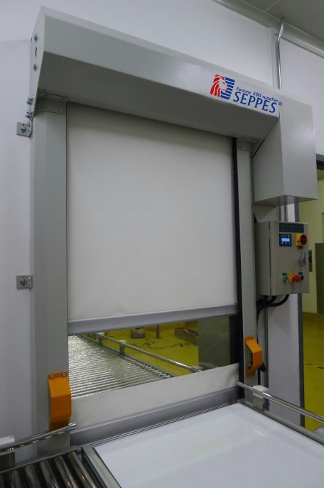
Record the Full Load Envelope
Describe the largest product and its support, including pallets, trays, wrapping and items that may project beyond the nominal load. Provide the direction of travel and explain whether loads can be skewed, stacked differently or stopped near the opening.
Show the conveyor bed, rollers, side guides and any transitions at the proposed door position. A building opening dimension alone does not describe the space needed by the load and the surrounding equipment.
Document the Mounting Space
- Photograph both sides of the opening and the conveyor approach.
- Identify the wall, frame or independent structure available for mounting.
- Record the space above and beside the opening.
- Show guards, sensors, services and nearby equipment.
- Mark dimensions that still require a site check.
Provide Inspection and Service Access
Explain how the door head, guides, drive, control equipment and adjacent conveyor components can be reached for maintenance. Ask the responsible teams to agree the necessary access and isolation arrangements for the complete installation. A door opening should not be assumed to provide a safe personnel passage into machinery.
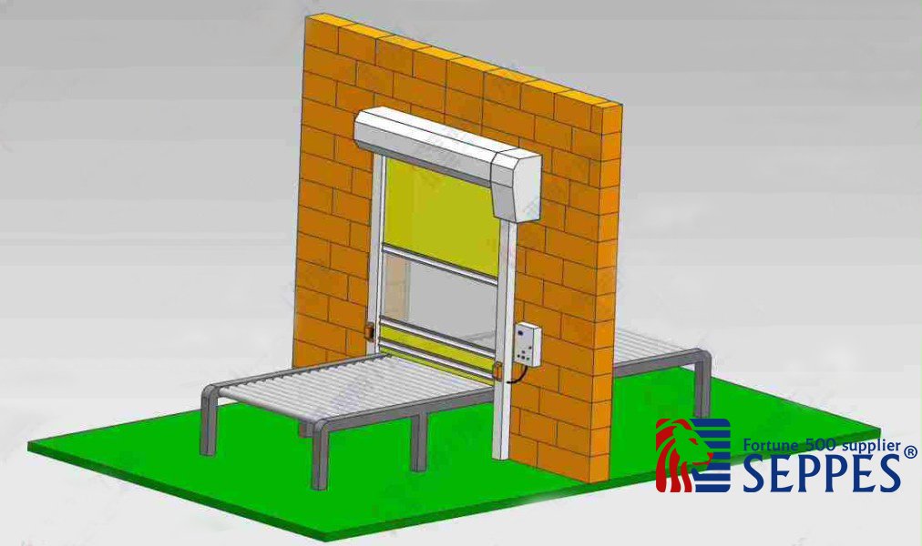
Separate Layout Questions from Control Questions
Once the layout is understood, define the interface responsibilities. Record which equipment requests transfer, which conditions must be confirmed and how an abnormal condition is handled. Those details depend on the selected door, conveyor and control system.
The dedicated control-interface guide covers the information to include in that discussion. It does not replace a model-specific control design, risk assessment or commissioning process.
Read the conveyor opening and control-interface planning guide
Review the Whole Safeguarding Arrangement
Personnel access, machinery hazards and the protective arrangement need assessment by the responsible specialists. A standard door sensor or an ordinary equipment-ready signal must not be assumed to provide the required machine-safety function.
For United States facilities, the OSHA machine-guarding overview provides context on machinery hazards and safeguarding. Applicable requirements and the suitability of the complete installation still need to be established for the actual project.
Read the OSHA machine-guarding overview
Send a Survey Package
Combine the load description, opening and mounting information, photographs and access requirements. Identify the door and conveyor models if they are already selected. Use the model-specific information to review power, materials, controls and any required test evidence instead of applying a generic historical parameter table.