OEM High-Speed Door Integration for an Automotive Production Line
Two high-speed equipment doors had to fit an automotive production-line frame and exchange commands and position signals with the OEM controller. SEPPES coordinated the mechanical drawings, mirrored motor positions, rear covers and interface details before factory assembly and commissioning.
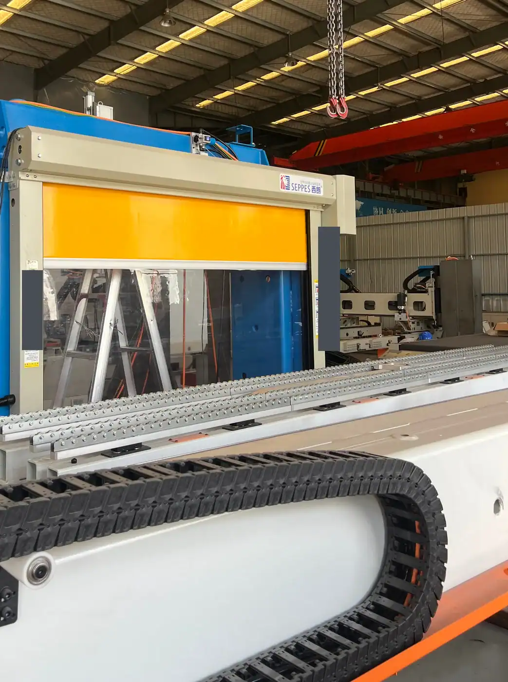
- Door package
- 2 equipment doors
- Clear opening
- 1,950 × 2,500 mm
- Motor arrangement
- Left & right layouts
- Factory acceptance
- August 2026
The door package had to become part of the equipment design.
This was an equipment-integration project. The door dimensions, mounting arrangement and controller interfaces needed to be agreed with the machine builder before manufacture.
The OEM Challenge
An equipment builder in China was assembling an automotive production-line package for an overseas project. The doors were to be mounted directly at the machine frame.
- Tight mechanical clearances around the opening.
- A left-hand and a right-hand motor arrangement.
- Commands and position feedback to coordinate with the line controller.
The SEPPES Response
The work combined a two-door supply package with drawing coordination and factory integration support.
- Opening and mounting details reviewed with the OEM team.
- Custom frame and curtain colours with rear metal covers.
- Door movement and agreed signal exchanges checked during factory acceptance.
Check the complete door envelope against the machine model.
The OEM supplied machine information for the door layout. SEPPES coordinated dimensional drawings and fitting information so the door could be incorporated into the production-line design.
| Design item | Project configuration | What an OEM should review |
|---|---|---|
| Opening | Two doors with 1,950 mm clear width and 2,500 mm clear height. | Confirm the opening around the complete moving load, equipment travel and the intended access route. |
| Motor position | One left-hand and one right-hand layout. | Mark the viewing direction on each drawing. Check clearances to columns, trays, neighbouring equipment and service access. |
| Frame finish | RAL 7032 grey frame finish. | Agree the colour reference, exposed surfaces and treatment required by the machine package. |
| Curtain and visibility | RAL 1028 yellow curtain with a transparent viewing section. | Define sight lines from the operator and service positions, together with the mechanical and process requirements. |
| Rear enclosure | Metal rear covers around the roll and drive area. | Include rear projections, cable access, cover removal and inspection space in the overall envelope. |
For surrounding structure and access-space coordination, review the custom door installation guide.
Write the signal agreement before the terminal connections are finalised.
The project used two-way command and status connections with the OEM controller. The list below describes interface functions; the final machine sequence belongs in the agreed controls design.
| Signal direction | Project interface scope | Questions to settle during integration |
|---|---|---|
| Door → line controller | Open-position and closed-position status outputs. | What defines the confirmed position? How will the controller distinguish a valid state from an unavailable or faulted signal? |
| Line controller → door | Opening and closing commands. | Who owns the operating sequence? How are conflicting commands, manual operation and a failed request handled? |
| Line and door-control coordination | An emergency-stop interface was included in the brief. | The responsible machine-controls team must define the required response and validate the complete arrangement for the machine. |
Separate Process Coordination from Safety Functions
Position feedback and opening commands describe the functional interface. They do not, by themselves, establish the required performance of a protective system. The machine builder should define the safety functions, components and validation scope through the machine risk assessment.
Agree Who Owns Each Connection
Keep a signal list with direction, electrical characteristics, terminal reference and responsible party. Confirm whether the machine builder, door supplier or another controls contractor supplies wiring, programming and witnessed tests.
For general machinery context, HSE’s introduction to machinery safety explains why guarding and controls need to be considered as part of the complete machine.
Prepare the signal agreement and responsibility list with the industrial door automation and interlocking guide.
Confirm the destination requirements at component level.
The door package was coordinated as part of an overseas equipment order. For another project, treat supply requirements and documentation as inputs to the design rather than assumptions attached to a product name.
Electrical Supply and Control Details
For a similar export machine, provide the actual supply voltage, phase and frequency, together with the control-signal requirements. Have the parties confirm the selected drive and control equipment against those values before production.
A destination country name is not a complete electrical specification. Keep the agreed supply and terminal information in the machine documentation.
Documents That Travel with the Equipment
Agree the language and revision of the installation information, wiring details, operating instructions and parts identification. Include door identification that remains traceable after the production line is shipped.
Confirm how settings and approved drawing revisions will be handed over to the team commissioning the line at its final location.
Factory integration brought the drawing and signal details together.
The project reached factory assembly and acceptance in China. The case concerns that integration scope; final-destination machine commissioning should be defined separately in the equipment project plan.
Review the Machine Information
The OEM and SEPPES teams reviewed dimensional and fitting information so the doors could be included in the equipment layout.
Manufacture the Custom Door Package
The two doors were produced with the agreed motor-side arrangements, colours, viewing sections and rear covers.
Assemble at the OEM Factory
The doors were mounted to the production-line frame and their control connections coordinated with the OEM team.
Complete Factory Acceptance Checks
Door movement, upper and lower position feedback and the agreed controller interfaces were checked for factory acceptance in August 2026.
Compare integration scope as carefully as the door size.
A building passage door and a machine-integrated door may share a flexible curtain, but their interfaces and acceptance scope can be very different. Begin with the function the opening serves.
| Your requirement | Review with the supplier | Useful deliverable |
|---|---|---|
| A door mounted on a machine frame | Door mass, mounting faces, projections and clearance for surrounding mechanisms. | A coordinated envelope and fixing drawing. |
| Frequent material-transfer cycles | The process sequence, requested cycle duty and door availability signals. | An agreed operating narrative and component configuration. |
| Protective access to a hazard area | The machine risk assessment and required protective functions. | A documented safeguarding design and validation scope led by the responsible machine team. |
| Shipment as part of an equipment package | Packing, identification, reassembly and destination support responsibilities. | A document and handover list that matches the final equipment arrangement. |
Prepare a brief that mechanical and controls teams can both use.
This checklist is for a new equipment project. The most useful first enquiry includes both the physical layout and the intended operating relationship.
Mechanical Package
- Machine model or dimensioned layout with every opening labelled.
- Required clear opening and the load or equipment movement through it.
- Motor-side preference with the drawing’s viewing direction marked.
- Mounting faces, rear-cover envelope and available service access.
Controls and Acceptance Package
- Supply voltage, phase, frequency and control-signal characteristics.
- Proposed commands, status outputs and terminal responsibilities.
- The machine’s operating narrative and separate safety-design requirements.
- Factory test scope, destination documentation and commissioning responsibilities.
Keep interface information usable after factory acceptance.
For another installation, include these items in the order and handover plan so the destination team can identify the installed configuration.
Agree the Witnessed Checks
Define the agreed normal command and position-feedback checks, the approved exceptional-condition tests and who witnesses the results. Record the settings and drawing revisions used during acceptance.
Support the Equipment Lifecycle
Keep the door identification, operating instructions, wiring information and service contact with the machine file. Review later changes to the machine sequence or guarding with the responsible teams before implementation.
Clarify the interface before committing the machine layout.
Can the motor be placed on either side?
This project used one left-hand and one right-hand arrangement. For another order, confirm the permitted layout with the supplier and mark the viewing direction so the mechanical and controls teams use the same reference.
Does a closed-position output establish a safety-rated interlock?
No. A functional position signal alone does not establish the performance of the complete protective system. The responsible machine team needs to define and validate the required safety functions and components.
Can a standard door drawing be used directly in an OEM model?
Use it as a starting point, then obtain the agreed project drawing. Confirm motor position, covers, cable access, mounting faces and service clearances for the actual machine arrangement.
What should be checked before an export machine is shipped?
Agree the factory checks, approved drawing revisions, settings, document language and destination responsibilities. The final list depends on the machine scope and the parties’ agreed acceptance plan.
What should I send for an initial review?
Send the machine layout, labelled openings, clear dimensions, proposed motor sides, electrical requirements and signal list. Identify the mechanical and controls contacts who can resolve interface questions.
Integrating a door into an OEM machine or production line?
Send the machine layout, door openings, motor-side requirements and proposed signal list. SEPPES can help review the door envelope, drawing interfaces and the scope of factory integration checks.